DESIGN OF A TRAFFIC SIMULATION
ContentsVehicle generation and Poisson process
Network xml file
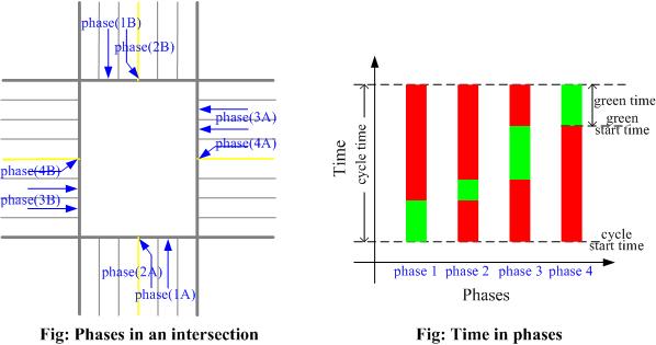
Phases
Vehicles move on links
Lane-changing
Traffic flow models
Traffic demand
No-parking Intersection
Changing route because of long-time waiting
Conflicts in intersections
Selecting loading-lanes of intersections
Home
VEHICLE GENERATION AND POISSON PROCESS
-----------------------------------------------------------------------------
If the generation of vehicles are considered as a non-homogeneous Poisson process (NHPP), then
To NHPP, one should know that
(1). the arrival count follows Poisson distribution with the parameter lambda
(2). the headway follows the Exponential distribution with the parameter lambda
where lambda is the average arrival count in unit time.
In simulation programming, therefore, the headway is usually employed to judge if it is the time to produce a vehicle in this simulation time step.
We do this in the ATS as follows:
At time Tc, if (Tc - H == Tl):
TRUE: Generate vehicle, and compute new H using Exponential distribution;
FALSE: Do nothing.
where Tc is the current time, Tl is the last time when vehicle is generated and H is the headway
Codes for headway (i.e., generation of Exponentially distributed variables)
////////////////////////////////////////////////////////////////////////////////
int Get_Headway(double lambda) //C++ code
{
int Int_Headway=0;
int Max_Number=1000000;
double ran= Get_Random_Number(0,Max_Number); //get a random number from uniform dist
ran=ran/Max_Number; //0-1
double headway= -(1/lambda)*log(ran); //x in Exp dist follows Uniform dist
Int_Headway= int(headway+0.5); //round
if(Int_Headway==0)
Int_Headway++;
return Int_Headway;
}
int Get_Random_Number(int Min, int Max) //say, Min=10, Max=20
{
int Ran= rand()%(Max-Min+1); //then: 0-10
Ran=Ran+Min;
return Ran;
}
////////////////////////////////////////////////////////////////////////////////
Top
NETWORK XML FILE
-----------------------------------------------------------------------------
Comments are made directly on the fragments of XML newtork file codes.
In the coordinate system of this simulation model, the point (0,0) locates in the left bottom corner
| <FixedOD> | //assign a fixed O-D pair |
| <Origin>39</Origin> | //link ID |
| <Destination>47</Destination> | //link ID |
| <Demand>-1</Demand> | |
| </FixedOD> | //-1: same with assigned in <Demand>, or generat prob of veh and should in [0,1] |
| <Demand> | //time-varying demand |
| <Time>0</Time> | //simulation time |
| <Value>5</Value> | //an origin generates 5 veh/min using binomial distribution |
| <Demand>-1</Demand> | |
| </Demand> |
| <MarginalPoint> | //the point at the edge of network |
| <Object_ID>0</Object_ID> | |
| <Object_Type>M</Object_Type> | //this type object should correspond to 'M' |
| <Object_Label>M0</Object_Label> | //the label can be displayed in the simulation frames |
| <x>2400</x> | //coordinate |
| <y>3000</y> | |
| </MarginalPoint> |
| <Cross> | //intersection |
| <Object_ID>0</Object_ID> | |
| <Object_Type>C</Object_Type> | //this type object should correspond to 'C' |
| <Object_Label>C0</Object_Label> | //the label can be displayed in the simulation frames |
| <x>400</x> | //coordinate |
| <y>3000</y> | |
| </Cross> |
| <Link> | |
| <Object_ID>0</Object_ID> | |
| <Object_Type>R</Object_Type> | //this type object should correspond to 'R' |
| <Object_Label>R0</Object_Label> | //the label can be displayed in the simulation frames |
| <Lane_Number>3</Lane_Number> | //the number of lanes that on this link |
| <Guidance_or_Not>0</Guidance_or_Not> | //is there guidance board on this link or not |
| <Detector_Location> | //location of G1Detector, used for Motivation 1 and doesnot work presently |
| <One>0</One> | //cell number |
| <Two>29</Two> | |
| <Three>0</Three> | |
| </Detector_Location> | |
| <Link_Start> | //start object of the link |
| <Object_Type>C</Object_Type> | //this link begins from Cross 0 |
| <Object_ID>0</Object_ID> | |
| </Link_Start> | |
| <Link_End> | //end object of the link |
| <Object_Type>M</Object_Type> | //this link ends from Marginalpoint 4 |
| <Object_ID>4</Object_ID> | |
| </Link_End> | |
| <Is_Origin>1</Is_Origin> | //whether this link is an origin, 1:true, 0:false |
| <Is_Dest>1</Is_Dest> | //whether this link is an destination, 1:true, 0:false |
| <Limited_Speed>28</Limited_Speed> | //maximum speed on this link, the unit of speed is m/s |
| </Link> |
| <Lane> | |
| <Link_ID>3</Link_ID> | //the link ID that this lane locates in |
| <Left_Turn>0</Left_Turn> | //turning direction: 0-false, 1-true |
| <Straight_Turn>0</Straight_Turn> | |
| <Right_Turn>1</Right_Turn> | |
| </Lane> |
| <Controller> | |
| <Cross_ID>0</Cross_ID> | //location |
| <Cycle_Time>100</Cycle_Time> | //simulation time |
| <Phase_Number>6</Phase_Number> | //should correspond to the following phase setting |
| <Phase> | //refer to Phases |
| <Phase_ID>0</Phase_ID> | |
| <Direction>1</Direction> | //0-left, 1-straight, 2-right |
| <Green_Percent>50</Green_Percent> | //percentage, e.g. 50 is 50% |
| <Green_Start_Time_Percent>0</Green_Start_Time_Percent> | //e.g. 10 is 10%, and greenlight begins at (10%*cycle time) |
| <Connect_Link_ID> | //the ID of Link that this phase connected |
| <A>1</A> | |
| <B>36</B> | |
| </Connect_Link_ID> | |
| </Phase> | |
| </Controller> |
Top
PHASES
-----------------------------------------------------------------------------

Top
VHICLES MOVE ON LINKS
-----------------------------------------------------------------------------
Link related
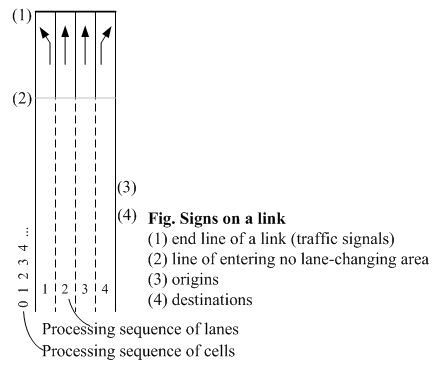
1. divide a lane into cells by a given length, and number them from the beginning of the lane;
2. Signs on a link: see the figure

Vehicle related
Target lane
Non-target lane (determined by vehicle's located lane and its turning direction)
How do vehicles run
1. In target lane, run
void CVeh::Drive_on_Dest_Lane()
2. In non-target lane, run and change lane (or may not this time)
void CVeh::Drive_not_on_Dest_Lane()
Processing sequence
It should be noted that the processing sequence in this simulation model is different from most of others.
In one time slice, we calculate a new location and speed of one vehicle and move it, then we process the next vehicle, ...
Thus, the location and speed of front vehicle used in most of vehicle moving model are corresponding to the ones of front vehicles at last time slice in ATS.
Deceleration and stop when approaching signs of a link (no front vehicle in front of signs)
Just consider a sign as a virtual front vehicle
1. Signs that are not able to be passed: set the location of the virtual front vehicle as the location of the sign, and the speed as 0.
include:
(1).red lights;
(2).non-target lane + line of entering no changing area;
(3).non-target lane + leave network at this link.
2. Signs that are able to be passed: ignore them, such as green lights.
Top
LANE-CHANGING
-----------------------------------------------------------------------------
Note: A lane-changing model is still needed.
Conditional statement
if (Probability + Bernoulli trial==true)
if the target cell on the target lane is empty
(when using car-following models, we need to check the cells around the vehicle)
Change lane
Realization in program
int CVeh::Change_Lane()
According to the processing sequence of lanes:
a. Processed lane to non-processed lane. If the changing space is available, move the vehicle to the new lane directly.
b. Non-processed lane to processed lane. Vehicle run by moving model first, then move the vehicle to the new lane directly if space is available.
Note: in the case, the speed of vehicle is not influenced by lane-changing maneuvers.
Special case: lane-changing lock
Description of problem:
See the figure
Solution in ATS: randomly decelerate the vehicle to speed between zero and current speed.

Note
Current ATS only allows one turning direction per lane. Codes need to be changed if want to allow more than one direction.
Question
Note that the same problem happens on the simulation model in www.traffic-simulation.de: choose "Traffic light"-> no truck -> stop -> start, then one will see vehicles stop in front of a red light, but when it turns to green, vehicles move side-by-side until queues discharge.
Therefore, is the interaction (or interference) between two side-by-side vehicles studied? Because the side-by-side driving is unusual. Most of time, one of the drivers will choose to decelerate or accelerate.
Top
TRAFFIC FLOW MODELS
-----------------------------------------------------------------------------
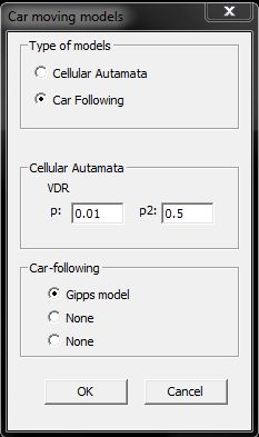
Car-following (CF) and Cellular Automata (CA) models are provided.
At present, Gipps model and VDR model are used, respectively.

Transformation between CF and CA models in one simulation model
In the simulation model, there are two types of cell lengths:
(1) is the pixel of a cell on screen. It does not only influence what the simulation looks; since two ends of a link are fixed at the beginning, it also determines the number of cells on this lane, which determines the real length of this link by multiplying length (2);
(2) is the length corresponding to the distance in reality. This length is used to calculate related traffic flow data, like speed.
Therefore, we are able to modify the accuracy of vehicles' movement by assigning different cell lengths to suit various types of traffic flow models:
In CA model, length (1) is 8 pixels, length (2) is 7 meters
In CF model, length (1) is 1 pixels, length (2) is 1 meters (which leads to the occupancy of more memories)
Note: since the length determines the generation of network, one has to choose the model before loading a network.
Default values of parameters of traffic flow models
| Gipps Model | ||
| TAU | 1s | Time step |
| Max_Speed | 28m/s | Free flow speed in freeway. The value of city street is set as 14m/s |
| A | 1.7m/s^2 | Acceleration |
| B | 3.0m/s^2 | Estimated breaking parameter |
| B0 | 2.8m/s^2 | Actual braking parameter |
| THETA | 0.5 | THETA is safety margin parameter, gipps sets THETA equals one-half of TAU |
| S0 | 6.5m | Vehicle length |
| VDR Model | ||
| p | 0.01 | Slowdown probability for moving cars |
| p2 | 0.5 | Slowdown probability for standing cars |
Trajectory
Trajectories of vehicles on a city street with traffic signals are drawn respectively using Gipps and VDR models.
(The data are generated by this simulation model, and the trajectory is drawn by a trajectory plotting program)


Top
TRAFFIC DEMAND
-----------------------------------------------------------------------------
1. Two types of vehicle generating are provided
(1) Random O-D. In the network file, each link is labeled whether it is an origin and a destination. An origin link and a destination link are randomly chosen to combine an OD in this type.
(2) Specified O-D. In <FixedOD> of the network file, an OD pair and its demand are specified.
Corresponding to two classes CRanDestOrigin and CFixDestOrigin inheriting from class COrigin in the codes
2. Making the demand time-varying (Note: the two following ways are mutually exclusive)
(1) Specifying in the XML file.
Demands in some time slices are specified in <Demand> of the network file, and the demands between these time slices are obtained using linear interpolation.

(2) Changing demands while the simulation is running.

Top
NO-PARKING INTERSECTION
-----------------------------------------------------------------------------
Before entering intersections, vehicles will check a region in the next (target) lane of the next (target) link as follows:
If the vehicle number in the region is smaller than the boundary vehicle number:
TRUE: The vehicles are allowed to enter the intersection;
FALSE: Waiting in front of the intersection.
In the codes, the region corresponds to the variable Checking_Region, and the boundry vehicle number Entering_Boundry
To different car-moving model, the values of these two variables are different, one can refer to file setting.h
To switch the function, select the "yellow intersection" on the toolbar.
Top
CHANGING ROUTE BECAUSE OF LONG-TIME WAITING
-----------------------------------------------------------------------------
When a vehicle has stopped and been waiting for changing lanes for a time t, we force the vehicle change its shortest route.
The situation indeed happens in particular when the demand is high. If we do not do this, the lane will be stuck because of the vehicle¡¯s long waiting time. The new shortest path will make the lane that the vehicle locates as the target lane, and then the vehicle can keep moving. If there is no path connecting the new next link and the vehicle will random choose a new destination that is close to the original one.
To save the computer resource, we only accumulate the waiting time of the vehicles in a small region indicated by LONG_TIME_WAIT_REGION in the codes. The time t is set by MAX_WAITING_TIME.
Top
CONFLICTS IN INTERSECTIONS
-----------------------------------------------------------------------------
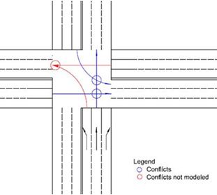
Two kinds of conflicts are designed, which are through-through conflict and through-left conflict. The conflict where two vehicles try to move into the same lane at the same time is not taken into account in this simulation. Vehicles running straight and in a platoon have the priority.

Top
SELECTING LOADING-LANES OF INTERSECTIONS
-----------------------------------------------------------------------------
(1) Through traffic. Choose the lane corresponding to current lane
(2) Left and right turn. Choose a lane randomly
(3) U turn. Choose the rightmost lane in the target link

Top
to be continued...